

Home · Resources · Publications
How and why we conduct airborne thermal infrared imaging
| Author(s): Volkovitsky A.A., Sklovsky S.A. |
Airborne thermal infrared (IR) imaging, alongside other remote sensing methods, plays an important role in geological and environmental investigations. Long used for military purposes, from the late 1970s it began to be successfully applied first in experimental and then in operational work to study the geological structure and environmental condition of survey areas, and to address a wide range of practical municipal-utility tasks.
A brief history
The widespread use of thermal imagers among airborne geophysical remote sensing tools in the USSR was marked by the introduction of the mass-produced civilian VULKAN thermal imager. Developed by the Azov Optical-Mechanical Plant to specifications from the Ministry of Geology in the late 1970s, it remained virtually the only instrument available for such work for a decade. The imager followed the then-conventional design of a two-channel optomechanical scanner recording images on photographic film. Its unexpectedly successful optical scanner design remains relevant to this day, accounting for the long service life of these instruments and their considerable scope for modernisation.
The earliest trials of thermal imagers were accompanied by several major developments that substantially expanded airborne thermal imaging capabilities. GNPP Aerogeofizika staff took an active part in this process. Their achievements included the first trials of an onboard thermal-image display system (1984) and mounting the thermal imager optical head on a gyrostabilised platform (1987). Nevertheless, photographic recording, as the only standard means of data recording, constrained the development of the method’s hardware. Only the rapid development of computing opened the way to what was essentially a new technology for conducting airborne IR imaging and processing its results.
Recognising the method’s considerable potential, Aerogeofizika initiated development of a digital thermal-image recording system. The work was financed from its own profits and entrusted to a development team involving staff from the Institute of Control Sciences of the Russian Academy of Sciences (IPU RAN). The following requirements were explicitly established:
- information must be recorded digitally on a technologically advanced, reliable computer storage medium (the onboard computer hard disk);
- information must be protected against recording errors by error-control codes;
- lossless compression coding of digital images must be used to reduce the volume of recorded data.
The recording system was based on a PC 386DX-40; the hardware interface between the thermal imager and the computer was implemented to a high standard by A.V. Sherstyuk (IPU RAN). The work also included developing methods and software for error-control compression coding, and system software for rapid, continuous recording of two spectral channels to hard disk and unrestricted real-time display (A.N. Drobotenko, Aerogeofizika). The system included software for decompressing recorded images into a conventional geophysical data format, together with tools for rapid viewing and processing corrections.
The results of six months of work by the development team entered practical use, replacing photographic recording and dispelling sceptics’ doubts about the system’s reliability. In autumn 1993, the first operational airborne IR survey of Moscow was carried out with digital data recording and complete processing on a PC.
Digital data, however, are not photographic film: they cannot be turned in one’s hands or viewed against the light. Development of software providing all the necessary methods for processing the acquired data began almost simultaneously. It is now impossible to draw a boundary between the hardware and software: they mutually determine the composition of the system as a single processing chain.
Certain prospects were associated with using a two-channel detector in a single optical and signal arm, which was expected to double the total number of channels and thus expand the system’s potential capabilities.
A year later, a thermal-imager signal-conditioning unit was developed, comprising:
- four channels for clamping and scaling the thermal-imager video signals;
- scalar and vector analogue-to-digital converters for measuring external signals;
- a logic controller for the optomechanical scanner drive motor;
- control and monitoring lines for all principal thermal-imager signals.
The signal-conditioning system was designed and built, all its components were debugged, the thermal-imager control-command exchange protocol was interfaced with the recording system, and four-channel recording with paired alternation was achieved without any loss of geometric resolution. Visual system-monitoring tools enabled not only observation of the incoming signals but also nonlinear calibration of measured values. The onboard software computes statistics for incoming image signals, allowing image correction directly during decompression.
Only the optical-head housing, mirror system, prism and motor remain from the old VULKAN… The upgraded thermal imager, now called Vulkan-4000, has no controls other than a communication channel with the onboard control computer, currently a Pentium-100.
Vulkan-4000 is a high-resolution thermal imaging system.
The airborne thermal infrared imaging hardware and software system developed by GNPP Aerogeofizika (Fig. 1) provides:
- reception of thermal-imaging signals in four spectral channels (2 visible, near-IR and far-IR) at high geometric resolution—up to 4096 points per scanned image line, at a scanning rate of 100–200 lines per second in each channel;
- real-time lossless compression of received data by a factor of more than two;
- data recording to the onboard computer hard disk without flight-parameter restrictions; recording-session duration is determined only by hard-disk storage capacity;
- recording of additional information: complete GPS data, gyrosystem parameters, flight altitude and up to 15 user-defined channels;
- control of thermal-imager operating modes: start-up, scanning frequency, video-channel gain, and the sequence and rate of sampling analogue channels carrying additional information.
The system hardware is built to a high standard using the most modern electronic components. It comprises an onboard computer plus two circuit boards, one installed as an internal add-on and the other mounted in a unit to which all system instruments are connected.
The system has a total field of view of 90 and an instantaneous field of view of 0.001 radian.
The thermal-imager operating-mode control channel was designed for an abstract thermal imager and can readily be adapted to any line scanner (VULKAN, ZIMA, etc.).
Since autumn 1996, the system has incorporated equipment for measuring and recording gyro heading and gyro vertical values. The earliest trials with these data demonstrated their considerable potential. A thermal image corrected using radiogeodetic data, the heading system and the radio altimeter proved to be practically a cartographic projection of the terrain.
The detector type is selected according to the user’s tasks. Our thermal imagers use cooled infrared sensing elements integrated in a single housing for the 3–5 μm (InSb) and 8–14 μm (CdHgTe) spectral bands. Temperature sensitivity is 0.1. Cooling is by filling with liquid nitrogen (77 K). Our thermal imagers also have visible-spectrum sensing elements, which, when used with optical filters, enable conventional multispectral imaging tasks.
Since 1997, the combined GPS+GLONASS GG24 receiver from ASHTECH has been used as the system’s principal instrument for aircraft positioning and helicopter guidance. Its main advantages are a high update rate (5 measurements per second), a convenient communication protocol and, most importantly, the quality of its results. Navigation software with extensive flight-control capabilities and all the indicators needed for aircraft guidance was created as the interface system. This improved the actual flight paths, reduced flight time spent entering survey lines, and reduced the processing required to correct geometric distortions in the acquired imagery.
These developments improved not only the quality of the information acquired but also the economic efficiency of the work, previously obscured by a host of reliability problems and organisational inconsistencies in flight planning and execution. In spring 1997, we were able to double the flight altitude without reducing data quality, thereby halving the number of survey lines. Combined with gains from improved helicopter guidance, this produced a substantial economic benefit. It also became possible to complete growing workloads within the very short seasonal periods favourable for imaging: as has long been observed, the best combination of weather conditions and heating-network temperatures for IR imaging lasts exactly one day less than is needed to image an entire city.
Thus, the technical development of GNPP Aerogeofizika’s airborne thermal IR imaging system has now reached a respectable level, even compared with foreign equivalents. The development experience accumulated enables not only high-quality operational surveys but also equipment upgrades commissioned by outside organisations. Aerogeofizika can likewise develop software to handle environmental-monitoring materials according to any requirements. One possible form of cooperation with clients is turnkey delivery of the entire end-to-end technology, including the hardware system and personnel training.
Thermal infrared image processing system
In principle, popular raster graphics packages and programs (ER Mapper, TNT mips, ERDAS Imagine, Corel Photo Paint, Paint Shop Pro, etc.) can be used to varying degrees at the processing and interpretation stage. However, we developed our own software package, mainly because of the particular characteristics of scanner imagery and the natural desire for the most effective tool covering the entire processing workflow.
The IRIT (Infra Red Image Tools) software package developed by us (A.K. Volkovitsky, A.N. Drobotenko and D.V. Kaplun) is an integrated operating environment, unique in its composition and operating principles, with a wide range of image-processing procedures. It provides the basis for a complete end-to-end workflow, from completed surveys to reporting materials. Its principal purpose is the interactive creation of thermal images at a defined scale. The output images can serve as a topographic base for subsequent interpretation, some of which is available directly within the program.
IRIT has a user-friendly multiwindow interface. A wide range of operations can be applied to each image window: windows can be moved, rotated, scaled, stitched together, cropped and so on. The program uses special file-access methods that enable large volumes of input data to be processed and displayed rapidly. A detailed Russian-language help system allows users to learn the program’s structure and functions relatively quickly.
With IRIT, users can:
- load and view superimposed source images in windows, in various data formats including vector formats;
- manipulate these windows using rotation, translation and scaling;
- use the mouse to designate points for subsequent stitching or coordinate measurement;
- perform coordinate-system and scale transformations;
- adjust the colour relationships of the input data;
- stitch images using the designated points according to the selected method;
- create curved cutlines in the seam area of overlapping, stitched images;
- save working images both as raster graphics files and as IRIT project files;
- save the selected image colour palette in a separate file and reuse it when converting processed raster data to popular formats (BMP, TIF);
- print any portion of the window mosaic at the selected scale on laser or colour inkjet printers.
Utilities extending IRIT’s capabilities use the package’s data formats and perform preliminary automated operations on input data. Although originally created as auxiliary tools, they are widely used in practice, especially for nontrivial processing tasks.
The utilities include programs for:
- preliminary assembly of source flight-line images, converting a continuous image file into adjacent fragments using navigation data; in some cases, the results are of reasonably sufficient quality for subsequent interpretation stages;
- processing corrections of images;
- extracting image fragments;
- increasing image sharpness (not to be confused with contrast!);
- rapid viewing of onboard data;
- converting data formats (to BMP and TIF), including application of a selected palette;
- modifying raster files (equalising their brightness, assigning part of the signal’s dynamic range to a transparent layer, etc.)
Details of the operational workflow.
We now turn to airborne IR imaging methodology, how onboard data are processed, and what our clients receive as a result.
The airborne imaging system is installed on a Mi-8T helicopter. To obtain an areal image of the thermal field, imaging is conducted along parallel flight lines spaced to ensure at least 40% image overlap.
After the flight, the data on removable hard disks are delivered to the office-based processing team. The onboard files are decompressed and processing corrections are applied immediately, equalising the brightness and, if necessary, the contrast of all flight-line images. The result is written to CD-ROMs and delivered to the client literally the day after the survey. The client’s specialists can immediately use these materials for rapid processing, since the data are accompanied by the necessary software (IRIT and a set of utilities). In principle, our work can be considered complete at this stage, because the client has all the technology required for further IR image processing. Most of our clients, however, request complete processing of the acquired information, up to creation of a scaled base for geographic information systems.
Such processing requires considerable time and specific skills. Using satellite navigation data and recorded heading, roll, pitch and flight altitude, the image is divided into quasi-linear fragments and semi-automatically “straightened”, that is, transformed to correspond to the actual flight conditions. In our assessment, the resulting corrected image files and IRIT project files meet requirements for scales of 1:5000–1:10000. Where accurate large-scale topographic materials are unavailable, they can be offered to clients as a scaled base. In some cases this is sufficient, and the materials from this processing stage are supplied to clients on CD-ROMs as the final deliverables.
A number of tasks, mainly related to monitoring municipal infrastructure, require higher scaling standards for the acquired IR images. In such cases, another processing stage is performed: transformation of the images to scale using a scanned topographic base. For cities, the scale is usually 1:2000. Topographic sheets are scanned and used as a base for transforming and stitching the thermal images using mutually identifiable points. The remaining steps are to create curved cutlines in the image seam areas and export the result to a window corresponding to the sheet boundaries. Whereas the aperture size (spatial resolution) of the source image is usually about 0.25 m, the scaled output is generated with a 0.5 m aperture, producing a 4 Mb file for 1 km2. This is very convenient in practice, while all features of the objects under study remain clearly visible. The resulting thermal images organised by map sheet can be used as a raster layer in any municipal GIS.
In some cases, we also print transformed IR images at scale, in colour or black and white. This is certainly a very impressive way of presenting the material and is particularly useful in client departments whose workflows have not yet been computerised.
Finally, for certain tasks (discussed below), we interpret the acquired materials and plot the results on a topographic base at scale. This stage still involves a substantial amount of manual work by highly qualified specialists, although we have recently been actively working to automate at least a significant part of the process, if not the whole of it.
Airborne thermal IR imaging: a high return on expenditure
In Russia today, widespread reductions in funding for all types of production activity have brought entire fields of research and applied scientific work into crisis. The market sector in which Aerogeofizika operates is no exception. Our traditional clients often lack the funds for scheduled repairs to their heating networks, product pipelines and other infrastructure. Surprisingly, under these conditions, airborne IR imaging does not create additional costs; instead, it enables funds to be spent in the most targeted and effective way, or even saved.
Airborne thermal infrared imaging addresses a wide range of tasks:
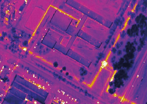
1. Determining the location and condition of underground heating networks, including detecting leaks. Airborne IR imaging is the only remote method that can promptly address these tasks and refine or compile heating-network layout maps. Depending on survey conditions, 70 to 100% of the network is mapped in a single survey cycle. Our experience in various Russian cities shows that this is a highly relevant task, since operating services often have no heating-network maps at all, or maps with substantial inaccuracies.
Thirteen years of experience in Moscow show that IR imaging should be conducted for monitoring twice a year—at the beginning and end of the heating season—and in the absence of substantial snow cover (more than 10 cm).
Our clients include the Fuel and Energy Administration of the Moscow Government, municipal enterprise Mosteploenergo, the Heating Networks division of Morsenergo JSC, municipal enterprise Teploremontnaladka, Moskompriroda, and the administrations of Tula, Lipetsk, Korolyov (Kaliningrad), Moscow Region, Reutov, Elektrostal, Lyubertsy, Ryazan and other cities.
Clients use the resulting materials to prepare and adjust annual repair plans. For municipal heating-system tasks, we generally interpret the acquired materials and plot the results of underground heating-network condition diagnostics on a large-scale topographic base.
As a result, our clients can not only recoup their expenditure quickly but also make a profit. The economic benefit increases the sooner the client can assimilate the information and use it to make management and technical decisions. For example, one cycle of airborne thermal IR imaging and processing for 1 km2 costs as much as replacing 10 linear metres of an average heating main. Thus, if analysis of the acquired materials reduces the required replacement length by 10 m, the client has already recovered the cost. If 20 m less is replaced, that is a 100% profit… This excludes the benefits of timely identification and repair of emergency sections, reduced make-up water requirements, more rational use of perpetually insufficient funds, savings on excavation (finally knowing where to dig…), and simply obtaining and using maps of one’s own heating networks (see Fig. 2)…
However, we currently see the greatest difficulties in achieving the most effective use of airborne thermal imagery. These include entrenched attitudes among specialists who traditionally distrust remote diagnostics, the still-low level of computer provision at client enterprises, and their inability to assign a couple of staff members and as many computers to work with the materials. Finally, there is simply an inability or unwillingness to account for money that is still not their own… One example is the analysis of the 1995 Moscow survey made a year and a half later by A.M. Goncharov, lead engineer of the Heating Networks division of Mosenergo JSC. It showed that 80% of the emergency or pre-emergency conditions indicated by thermal imagery were confirmed—that is, eventually developed into full-scale failures. Had these data been used in time, direct losses of 4 billion roubles could have been avoided. Optimising major-repair plans using IR imagery, together with analysis of the linked asset-record database, is equivalent to increasing repair funding by approximately 30% (about 120 billion roubles for 1996). This concerns the infrastructure of just one client. Unfortunately, as far as we know, in this particular case these gains remained on paper…
Here is another example of the effectiveness of airborne IR imaging, from the same year. Using the imagery, specialists at municipal enterprise Mosteploenergo identified 280 sections with heat-transfer-fluid leaks, including 163 pinhole leaks. All leaks were eliminated either promptly or through scheduled work. The economic benefit of the work was twice the expenditure. As a regular client, Mosteploenergo not only makes productive use of thermal imagery but frequently initiates new levels of processing and sets requirements for hardware and software. According to chief engineer V.P. Kashcheev, airborne IR imaging, as a tool for remote diagnostics of municipal heating infrastructure, has now become an integral part of the heating-network maintenance process.
2. Mapping and diagnosing the condition of product pipelines, including leak detection. This primarily concerns oil and gas pipelines, which extend for many thousands of kilometres and whose service life of more than twenty years implies substantial wear. Both have temperatures elevated relative to their surroundings, so even underground pipelines produce thermal contrasts sufficient for detection. Our experience shows that airborne IR imaging of these facilities can be conducted at low altitudes (up to 100 m), with an actual resolution of 0.1–0.2 m. Images of this quality clearly reveal details of the pipeline’s thermal signature, sections affected by groundwater inundation (and therefore increased corrosion risk), and locations where hydrate plugs develop. Leak sites appear differently: on gas pipelines they are high-contrast, very cold local areas, owing to adiabatic gas expansion; on oil pipelines they are areas warmer than their surroundings. Oil-spill areas are mapped well.
3. Monitoring the condition of water bodies.
Thermal imaging can detect unauthorised industrial and municipal wastewater outfalls, including low-discharge, low-contrast releases unlikely to be identified visually. This makes it a principal method for addressing environmental problems in heavily industrialised areas. It does not matter whether these discharges are substantially warmer or colder than the receiving waters. This task can also be addressed during IR imaging of urban areas, although the best results are naturally obtained from dedicated night-time surveys with the thermal imaging equipment adjusted exclusively for water (see Fig. 3).
Airborne IR imaging is also highly effective in searching for oil pollution patches on water in areas of heavy tanker traffic and possible ballast-water discharge, near major ports, or following accidents and disasters involving petroleum spills. Unlike visual mapping methods, thermal imaging detects films only micrometres thick, that is, very slight contamination.
Equally distinctive are the capabilities of airborne IR imaging for locating zones of subaqueous discharge from the upstream pools of reservoirs and zones of subaqueous fresh groundwater discharge into the sea. We conducted such work on Georgia’s Black Sea coast in 1982, at Lake Balkhash in 1986, and elsewhere.
In arid climates, identifying leaks, including localised leaks, from irrigation systems and surface water-conveyance infrastructure is an important task.
Monitoring storage facilities for liquid industrial waste, which is generally highly toxic, is of considerable interest for environmental protection. IR imaging can detect leaks from such facilities at their inception, thereby preventing severe environmental consequences.
4. Detection of concealed spontaneous-combustion sites in waste disposal grounds (municipal landfills), peatlands and forests, especially in their early stages, enables them to be contained and extinguished promptly at minimal cost. Imaging is conducted during patrol flights at altitudes of 1–2 km in summer, the period of greatest fire risk. Fire sources can be located in real time or through post-processing on the ground. At peat-extraction enterprises, peat stacks containing incipient internal fires can be identified.
5. Identification of groundwater inundation and waterlogging from thermal imagery relies on the increased thermal inertia and somewhat reduced albedo of wet areas in the upper soil layer. This task is addressed most effectively in natural landscapes. In urban agglomerations, asphalt surfaces, dense development and similar factors complicate it. Nevertheless, in some cases, especially in areas with open layouts, thermal imagery can identify inundation affecting buildings and structures. For example, airborne IR imaging in spring 1997 identified a groundwater-inundation zone affecting the central building of the memorial complex on Poklonnaya Hill in Moscow.
6. Monitoring the condition of filtration and aeration fields.
While carrying out thermal monitoring of Moscow, we repeatedly imaged the Lyublino filtration fields (LFF). The resulting materials reliably map areas of active biothermal processes within the LFF, indicating current wastewater inflow into individual cells of the fields, contrary to official information. Localised water discharges into flow-regulating ponds are also identified. Monitoring allows the dynamics of exothermic processes to be tracked and a predictive model of their development to be constructed, thereby determining the sequence in which the area should be developed for construction. Thermal imagery shows that the mass housing construction undertaken in the southwestern LFF, where the most active processes occur, represents a flagrant disregard for environmental requirements applicable to development sites.
7. Assessing road-surface condition.
The condition of roads in our country has always left much to be desired… Funding for their repair and maintenance has never been sufficient. Remote diagnostics of their condition is therefore particularly relevant, especially when high-productivity, relatively inexpensive methods such as airborne IR imaging are available. Road-surface quality depends on the quality of the underlying base. Loosened areas of the base are the first to deteriorate because of their increased permeability. Such areas generally exhibit excessive water saturation beneath the pavement due to groundwater and precipitation, which can vary substantially with weather conditions. Constant changes in water content cause weather-related deterioration of the base, especially in winter, when freezing ground heaves the pavement, as well as through leaching and washout of fine particles—a common process in the soil aeration zone. This in turn causes pavement failure and subsidence.
Consequently, water-saturated road sections warm more slowly because of water’s higher heat capacity and evaporation under solar radiation. They appear as dark (cold) patches in daytime thermal images of the asphalt surface.
In 1995, commissioned by Tulavtodor, we conducted experimental and methodological work on a section of the Tula–Venyov road, verifying thermal imagery with a combination of ground geophysical methods (electrical prospecting and ground-penetrating radar). The results showed that airborne IR imaging can successfully monitor the condition of paved roads. The reliability of the results increases with repeat imaging in the evening and morning, immediately after sunset and just before sunrise, because water-affected areas are interpreted as zones of thermal-field inversion.
The most efficient investigation procedure consists of airborne imaging followed by detailed ground-based investigation of areas with damaged pavement. The integrated results allow road sections to be classified as being in satisfactory condition, requiring superficial pavement repairs, or requiring work to strengthen the base.
Airport runways, which are essentially specialised road surfaces, are investigated in the same way.
The imagery of Tula Airport acquired in the same year, 1995, speaks for itself (see Fig. 4)…
8. And more generally…
In fact, airborne thermal imaging has a much wider range of capabilities. These include structural-tectonic and lithological mapping for geological tasks in exposed areas; power-line surveys; identification of talik zones in permafrost areas during engineering geological investigations; investigation of karst and landslide areas; land-management tasks; mapping underground nuclear-explosion zones at test sites; and much more. We have even counted whitecoat seal pups at seal breeding colonies on the White Sea coast… Who knows, reader—perhaps this article will inspire you to use IR imaging for something even more exotic. We are ready to consider any proposals and projects.
If you commission survey work from us, you will be pleasantly surprised by the completeness and quality of the results. As the napkins in a Chinese restaurant say: TRY this dish.
References
Antypko A.I. Fundamentals of remote thermal monitoring of the geological environment of urban agglomerations. Moscow: Nedra, 1992.